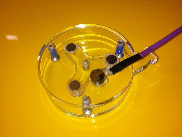
Laser cutter coolant flow sensor. The concept was to have a sensor that wasn't inline with the coolant line and couldn't restrict the flow if it seized up. I'm sure that the design is scaleable within reason for other projects. It is simply tywrapped to the outlet end of the coolant pipe and dunked in the coolant reservoir/bucket. The sensor is a simple hall effect switch.BTW, if anyone knows how to embed a YouTube link to movie, let me know - the movie is at the bottom :-)The sensor was cut from some scrap 6mm acrylic - a length of 2mm dia stainless rod for the shaft and three 8mm neodymium magnets let into the impeller (the drawing marks the centres, drill them 3mm deep with a bullet/butterfly drill). Detector is a hall effect sensor - each time a magnet passes, the switch comes on - I've indicated something similar to the old one I used. I initially tried the system with a reed switch, but the reeds I had were non too sensitive - YMMV. Any old hall effect sensor should work fine - you'll need to rake through your local suppliers catalogue. Ensure that BEFORE fitting and gluing the magnets that you have the common poles all facing the same direction and that pole direction activates the hall effect switch. 'Normally', the hall effect switch will switch on when activated by one pole of the magnet (but not the other pole) - generally able to sink at least 20mA. I purposely haven't shown any wiring as the sensors may be different - keep your other components out of the water :-) You can use thin cyano or plastic model cement to keep the magnets in.One side of the sensor is tapped to receive three M4 stainless screws with a bit of plastic spacer tube to keep them apart (you could of course just drill them 4mm and use stainless locknuts). I did laser cut acrylic spacers for the first model, but if you cut them from the same sheet, they're going to be the wrong thickness without grinding them down. The centre hole on the impeller needs to be drilled accurately at 2mm and the inside faces of the outers need to be again drilled partially through (4mm) to trap the ends of the shaft. A couple of wee plastic washers on the shaft will keep the impeller roughly centred - I used old transistor mounting bushes - you want a 'rattling fit' so that the impeller doesn't jam. Keep the gap between the plates to about the ID of your pipe.The sensor was wired up to a length of three or four core security cable - heatshrunk to the sensor legs, then the whole end dipped in clear model aircraft dope a few times - giving about ten mins between 'coats' - to keep the water out. I guess I could have used silicone sealant, but I was in a hurry and silicone is messy - I've used dope a few times before and the method works just fine. The sensor was held into the rectangular hole with a 'popout' of acrylic from something I had been cutting before - I keep a scrap box of all the bits that end up on the crumb tray under my laser cutter - they eventually come in handy for something :-) The drawing shows a small 'fork' that should be better than the small disc I had to hand.The output end of the coolant pipe from the laser is simply tywrapped to the sensor assembly and wire so that the pipe is directed at the impeller - there's a notch in the acrylic for the purpose. The hall effect switch runs from 5V, so you can connect it to any monitoring system - I like a simple approach and just use an LED attached to a resistor - the LED flashes to indicate flow, I just want to know that it's rattling round :-)The whole assembly is dunked in your coolant reservoir/bucket/container - if the impeller jams up, it doesn't restrict the coolant flow and won't cause any overheating probs. Of course, you can connect the sensor to anything you like - calibrate the whole gadget too if that's your thing - even add a temperature sensor etc. One suggestion was to incorporate a simple 555 missing pulse detector that fired an alarm if the impeller stopped - I'm sure that there will be many modifications !!Had a brainwave this morning, for a simple system, you could hack a bike computer setup (don't think a wireless version would work). The speedo would indicate - well speed I suppose :-) - it's conceivable that it could even be roughly calibrated.
- 0 inches x 0 inches x 0 inches
- this product is 3D printed
- 16 available colors
- material is a strong plastic
- free delivery by May 02
- 0 parts