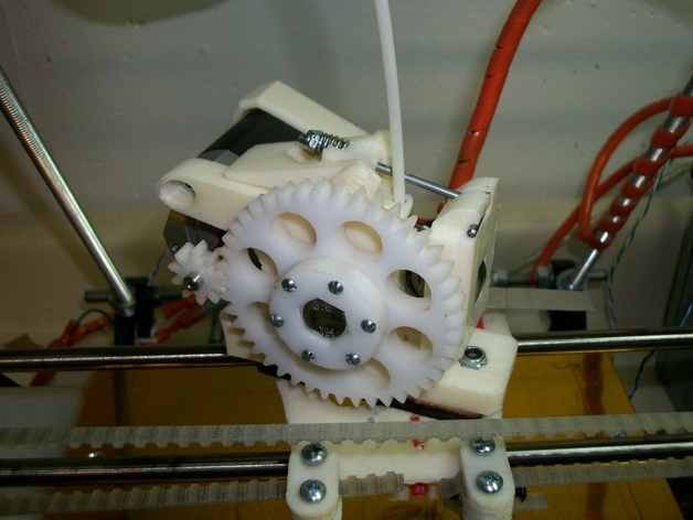
After using a gregfrost extruder on my Prusa for a while, I decided I wanted to make a few tweaks to the basic design: replace the hobbed bolt (I found it too strip-prone) with a large-diameter filament driver that requires no machining a spring-loaded over-center latch on the idler arm, allowing opening the idler without unscrewing anything After assembling it and running a few test parts, I put it to work building parts for sublime's printed lathe, around 45 hrs of runtime with 14 hrs for the longest single build, and didn't experience a single hiccup. I have since run it at up to 100mm/s, which it handles fine. The extruder body has mounting provision for the Makergear hotend. Zip file contains the Solidworks 2011 source files.If you have a gregfrost extruder, you can re-use all the parts of it except the body, the idler arm, and the hardware connecting the two. Print the extruder body in ABS. No support should be required; there are built-in removable supports where needed. The rest of the parts can be ABS or PLA as you prefer. Driver drum The filament driver drum can be made from a McMaster-Carr aluminum spacer P/N 92510A797 (current price $2.32). The drawing shows the dimensions if you want to machine your own. Use the drill jig to tap drill for 2 6-32 holes in the drum (if the drum is loose in the jig, tap 2 of the jig holes for 6-32 clamp screws). Tap the holes & install 2 6-32 x 3/16 setscrews. Clamp an 8-32 tap into the crank handle for the hobbing jig with a 6-32 screw on each side. Tap the small holes under each bearing cutout in the hobbing jig 6-32 and insert a screw in each one. Assemble the drum into the hobbing jig with 2 608 bearings and an M8 bolt & nut, tightening the drum screws to align the drum centerline with the hobbing jig centerline. Insert the tap/crank into the jig, snug the bearing screws just enough to put the drum in contact with the tap, and spin the crank a few times. Remove the nut and pull the bolt & drum out to check that the hobbing is indeed centered, adjust if necessary, and re-assemble. Start cranking, tightening the bearing screws periodically until the hobbed groove is about 1/2 filament diameter deep. Latch link The wire link for the latch is made from a steel wire pushrod made for R/C airplanes, so you'll probably have to visit a hobby shop to get one. If you can't find one locally, see http://www3.towerhobbies.com/cgi-bin/wti0001p?&I=LXD871&P=7 . Bend to the drawing. Assembly Cut a piece of the leftover pushrod wire a bit shorter than the width of the latch lever, and use it to attach the pivot block to the lever. Cut two short pieces of filament to act as pins for the lever, gluing them to the tabs on the body. Insert the threaded end of the wire link through the pivot block and put on the idler spring and 4-40 locknut. Install the main bearings, big gear, bolt, driver drum, and locknut. Adjust the driver drum position so the hobbing is in line with the filament path. Install the idler bearing and its pin into the arm. Use a 6-32 screw to hinge the idler arm to the body. Assemble the extruder, hot end, motor, etc. Watch the length of the extruder mounting screw by the idler, if it's too long it could prevent the idler from opening fully.