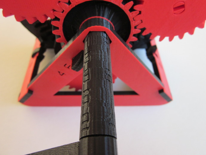
Have you ever wondered how an automatic transmission works? I did, so I looked it up and then designed this desktop model. It has six forward speeds and one reverse. Real automatic transmissions have a hydraulic or electrical system that engages different clutches and brakes to shift gears depending on the driving situation. With this model you control those simplified brakes and clutches yourself. The clutch is actuated by sliding the drive shaft through to different positions (which each have two gear markings), while three separate brakes each also have two gear markings. You select a gear by engaging the brake and clutch position associated with your desired gear. See demonstration video: http://www.youtube.com/watch?v=-FyC3dn3HJYI tried to design the gear ratios to be fairly close to what some real cars use, and this is the result, where the input is the crank and the output is the annulus: 1st gear: 1 : 4.29 2nd gear: 1 : 2.5, 71% increase 3rd gear: 1 : 1.67, 50% increase 4th gear: 1 : 1.3, 28% increase 5th gear: 1 : 1, 30% increase 6th gear: 1 : 0.8, 25% increase Reverse: 1 : -3.93The OpenSCAD file is included and is highly parametric in case you'd like to play with different gear ratios. If you select a different number of teeth, it will print out the resulting gear ratios at the beginning of the output. I also used Matlab to investigate more thoroughly how the gear sizes affected the various ratios. I used transmission.m as an aid in optimizing the ratios to be somewhat evenly spaced.This was all printed in PLA at 120 mm/s on a Replicator 1 with Sailfish firmware, default layer height (0.27mm). Everything came out perfectly on the first print. I swear, complex models don't have to be difficult, and who needs glue when you can print snap-fits?All the STLs are there if you want to print the pieces individually, but using the plates is quicker. Print one each of stand.stl, gears.stl, carrier.stl, shaft.stl, crank.stl, handle.stl, and three each of planets.stl and pins.stl. To make the labels more visible, you can pause and switch colors a couple layers into stand.stl.Each of the stand pieces has a brake, which is a separate element that is permanently captured by the larger piece. Make sure these can rotate freely (they can require some force to free if your printer leaves any strings). Then assemble the stand as shown in the pictures (they're designed to press-fit, so no glue should be required). The herringbone gears are tricky to assemble because they cannot slide past each other, but they run smoothly and don't require thrust bearings like the helical gears in real automatic transmissions. All these steps are shown in the photos above. Start with the planet carrier right-side-up and insert two medium-length pins into two inner holes and snap idlers (smallest planet) onto them. Then mesh an upside-down sun gear to both of them. Finally, mesh the last idler with the sun and push its pin down through from the top to secure it.Next, mesh a medium planet with an idler and push a long pin through from the back of the carrier to secure it. Attach a large planet to the other side of this pin (on the back of the carrier). Next, set the assembly with the idlers down in the middle of the annulus. Mesh the other two medium planets with the idlers and annulus and make sure they line up with their holes. Set a large planet on top of one of those holes and clock it until the flat sides of the holes line up between the large and medium planet. Then push a long pin all the way through to lock them together. Mesh an upside-down sun gear with the two large planets, then attach the last large planet the same way (again, being careful with the clocking so that the pin will go through). Now that assembly will hold itself together. Put it in the stand so that the annulus faces the side that says "1 3", then insert the drive shaft from that same side. You may have to rotate pieces to get the hexagonal part to slide through. Use the short pins to attach the crank and handle to the drive shaft, and you're done.Mine started out pretty tight, but after greasing the pins and spinning it for awhile it loosened up. Mostly I think it had to grind off the tiny bumps and strings that form in the gear teeth. UPDATE: I've added front_loose.stl and back_loose.stl for anyone who is having trouble getting the brakes to free up. They use the same tolerance (0.25mm), but I've opened up the rest of the space around them to make them easier to break free. Note the stand plate doesn't use these, so you may want to make your own printing plate.
- 0 inches x 0 inches x 0 inches
- this product is 3D printed
- 16 available colors
- material is a strong plastic
- free delivery by May 02
- 0 parts

