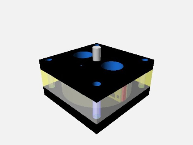
Reagent Robot ============ The idea here is to remove human variability and provide for automated data collection with low cost chemical reagent tests for common water conditions such as Ammonia, Chlorine, Nitrate/Nitrite, and pH. Currently, the electronic sensors for those test are very, very expensive and require frequent replacement. This thing shows a possible design for the reaction chamber where the chemical indicator is added to the sample water and LED/photodetector combination is used to test the color of the resulting mixture. This design is not meant to be a final product, but instead just a starting point. The bottom plate simply has a hole drilled part way through for the stirrer/cleaner shaft to sit in. A single ball from a bearing would be dropped in the hole to reduce friction and extend the life of the "bearing". Initially, this plate could be plex, but eventually should be something more durable. The center (clear) area is a square block of plex with a large circular hole in the middle where the sample will be held. A stirrer / cleaner made from metal with a vertical shaft turns in this space to both stir the sample and reagent and to clean the sides of the chamber to ensure consistent optical performance over time. The shaft exits the top plate and connects to a small stepper or gear motor which is not shown. If the recommended injector is used, the motor of the injector could be used to turn the stirrer / cleaner, but this is not necessary to the design. The black top plate has holes for the inlet of water from the valve (not pictured) and exit of the prior sample (to drain). Not shown is the small hole for the inlet of the reagent from the injector pump. An animation might help: https://www.youtube.com/watch?v=5hVGm40IKCw Reagent injector: http://www.thingiverse.com/thing:219281 looks just about perfect. Parts list: https://docs.google.com/spreadsheets/d/1VqRxvLsWpltaBc5tXhsEXb2C1_wAgTpsExAs6M93qz8/pubhtml See also: https://hackaday.io/project/4197-reagent-robotA few notes on construction on the off chance someone ever bothers to make one of these: I was figuring on 1/4" plastic for the layers of the chamber, and 18 gauge stainless steel for the paddle. The thickness of the plastic needs to work out so that the chamber height is the same as the height of the paddle. So I would cut layers of plastic for the chamber first, then make sure the plastic is an even divisor of that. With the files as provided (you can change them in Customizer), the paddle should be 1/2" high so two 1/4" plex layers will make the chamber fit the paddle. If you have 1/16" plex, then you must cut 4 layers. Hope that makes sense. Then the layers are held together with nuts and bolts... #6-32 by at least 1" long. The nuts and bolt for the paddle will be 2mm so M2's by 3 or 4 mm long. With matching nuts. Or #2-56 bolts and nuts. Tiny. Needs a shaft and coupler unless we can find a stepper motor with a long enough shaft: "Metal shaft, 5mm" or 3/16th would probably work. Couple it with a bit of 5mm ID tubing. 1 CUT ALL THE SHEETS: Made by laser cutting 1/4 inch plexi sheets and stacking them to form the bottom plate, reaction chamber (the center clear area) and the top plate. Those are the .dxf files on Thingiverse. In the picture/video, the top and bottom are shown as dark, but that would probably be accomplished with paint or something else on top and bottom of the otherwise clear stock. The bottom plate simply has a hole drilled part way through for the stirrer/cleaner shaft to sit in. A single ball from a bearing would be dropped in the hole to reduce friction and extend the life of the "bearing". Initially, this plate could be plex, but eventually should be something more durable. The center (clear) area is a square block of plex with a large circular hole in the middle where the sample will be held. A stirrer / cleaner made from metal with a vertical shaft turns in this space to both stir the sample and reagent and to clean the sides of the chamber to ensure consistent optical performance over time. The shaft exits the top plate and connects to a small stepper or gear motor which is not shown. If the recommended injector is used, the motor of the injector could be used to turn the stirrer / cleaner, but this is not necessary to the design. The black top plate has holes for the inlet of water from the valve (not pictured) and exit of the prior sample (to drain). Not shown is the small hole for the inlet of the reagent from the injector pump. 2 INJECT! INJECT! INJECT! Metered injection of liquids is a solved problem. See: http://www.thingiverse.com/thing:219281 Drill a hole in the top plate to allow the injection of reagent and attach the lines for the inlet of sample water, outlet of sampled water, and injected reagent. Figure out how all that is going to fit with the shaft from the stepper motor, and how the motor will be mounted. Curse, throw everything away, and redesign. 3 GET IT TOGETHER Assemble the stirrer, bottom plate, chamber, top plate, all inlets and outlets, the stepper shaft drive, and stepper. Add a stepper motor driver :cough: probably one of those little Pololu drivers will be fine, and an Arduino. Oh, and you need a driver for the inlet valve. Sure would be nice to have an interface board. :cough: The standard RAMPS would be overkill... An obvious choice would be the Adafruit motor shield which should drive a valve as well as it does a motor: http://www.adafruit.com/products/1438 4 YOU GOT TO MOVE IT, MOVE IT! Program the Arduino to open and close the valve, cycle the servo to inject reagent, and clean, stir, and mix the sample in the chamber. 5 I CAN SEE CLEARLY NOW Add the LED's, or NeoPixles and a light sensor. Probably something nice like: http://www.adafruit.com/products/1334 And program the Arduino to take readings with each light source. You might be able to shine a white light on it and use the RGB sensor to do it all in one reading. Remember to do a calibration / turbidity reading before adding reagent to compensate for water quality and changes in the light source / sensor. 6 GO FORTH AND SPREAD THE... READINGS... TO ALL THE LAND! Wire it back to a PC or Pi or an ESP8266 or whatever and tweet the readings hourly or whenever.
- 0 inches x 0 inches x 0 inches
- this product is 3D printed
- 16 available colors
- material is a strong plastic
- free delivery by Mar 08
- 0 parts