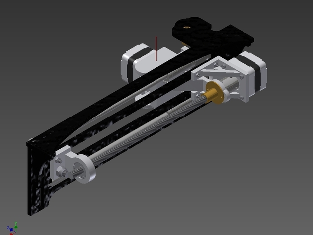
This replaces the X-Axis Belt driven system with a Lead Screw Driven System. All the parts are untested as of this moment. Note that a Hole for the M4x20mm screw will need to be drilled in the Gantry. I will make some detailed instructions when I'm satisfied that this design works. Extra parts to purchase: (4) M3 x 8mm screws (2) M3 x 12mm Screws (2) M3 x 35mm Socket Head Screws (required only for Single Body Extruder) (8) M3 Hex Nuts (1) M4 x 20mm Screw (1) M4 Hex Nut (1) 5/16-18 x 1" Button Head Screw (1) 5/16-18 Lock Nut (1) 7/8" Internal Retaining Clip (OD .943, THK 0.046) (1) 3/8-12 ACME Lead Screw Nut (from QU-BD Store) (1) 3/8-12 ACME Lead Screw: OneUp = Order a Second ACME Lead Screw from the QU-BD Store TwoUp = will need to order and Cut an ACME Lead Screw to 10 1/2" Long (1) 3/8-16 Hex Jam Nut (McMaster P/N: 96557A114) for Tensioner Note: Be sure your X-Axis Stepper Motor shaft has not been bent. If it is swap the X-Axis Motor with the Y Axis motor (do not replace it with the Z or the bend will affect your prints). The parts should be updated and work properly. Please let me know of any issues you find in the files.At this point you should be good to go. Any wobble is most likely caused by a bent stepper motor shaft and will be apparent right away. If the motor seems to be hanging or stopping first try tightening the Coupler and verifying its secure. Then try adjusting the stepper motor speed in the EEPROMS. Worst case, a bigger Nema 17 Motor may be needed as the limitations on these Custom Wiring Motors from QU-BD may not be able to handle the change.
- 0 inches x 0 inches x 0 inches
- this product is 3D printed
- 16 available colors
- material is a strong plastic
- free delivery by May 03
- 0 parts