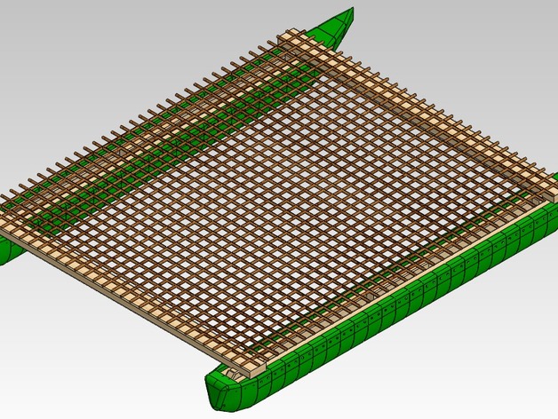
Thingiverse has enough toy boats now, so I designed these segments for a 3D-printable ama/outrigger that could actually be used for hull(s) as part of a wee catamaraft or an outrigger canoe. (Starting with a beautiful excited ms-paint concept sketch that preceded a couple days of thought and a night of CAD :)http://en.wikipedia.org/wiki/Ama_%28sailing%29 http://en.wikipedia.org/wiki/Outrigger_canoe http://en.wikipedia.org/wiki/CatamaranSTL and STEP files are provided of original blanks and my 3x2/4x2 model, so that hopefully you can adjust this design to whatever size you want and fittings you have available. A SolidWorks eDrawings file is also available to get a quick look at my suggested assembly. Actual rope lashings are not shown, but I hope you can figure out something as simple as cris-crossing a rope to lash 2 beams together, since representing it in a CAD drawing is tedious. Not all the nails are in this diagram either due to defining mates for either end of the assembly being a pain (I've learned to use octagonal holes outside the X-Y plane instead of circular, for ease of printing).My current pre-holed versions of these models are adjusted so they should fit nicely with 6ft-long beams of 2x3" or 2x4" wood cut to standard North American softwood lumber dimensions: http://en.wikipedia.org/wiki/Lumber#Dimensional_lumber The design shows 6ft 2x3's in the sides holding the outriggers straight, but this could be achieved with shorter scrap lengths by staggering them along either side. A few 1ft-long 2x4's are shown cut to a roughly appropriate shape, but longer beams would be better, and the lateral beams (aka) are 5ft lengths of 2x4" with a notch on one flat side near either end to aid holding position to lashing points. The nails shown are some 3mm by 45mm aluminium roofing nails that I've just got hold of (if you're going to use metal fasteners at sea, high-grade stainless steel, admiralty brass or aluminium is a must), and there are holes between each designed section that could be used for 6x25mm dowels.Not shown in pictures yet is a hole that I added across each bow, which could have rope tied through it for rigging or carrying. The two holes shown at the back could be used for a pivot-and-pin adjustable rudder, so that it can be pulled up when launching/beaching and dropped&pinned into place during strong winds.I might add some more part designs later to enable a very small sail to be rigged easily; when I have time of course, there are so many other fun and useful projects that I could try working on.Bonus points if you can build one with a sail, solar panel, battery, Arduino GPS Shield, sensors and actuators, and have it circumnavigate the globe autononmously. Zero-fuel automated freight is one goal that I hope we can aim to develop towards (and past :)P.S. [1] I'm currently about halfway through 'Multihull Seamanship' by Michael McMullen, which I was lucky to find on a local second-hand bookshelf. I've learned a bit so far about the speed and stability advantages that come with multi-hull vessels, and about design considerations, for instance in a trimaran you should try to keep your outriggers fitted such that they barely touch the sea while sailing straight, and at an angle such that when your ship heels (rolls, in aero terms), the middle hull and outrigger are roughly at symmetric angles to each other from vertical/horizontal, and a curved support arm/wing/aka is better at taking the stress of heeling against such a float (attempted to display in my sketch up top).[2] Because: http://en.wikipedia.org/wiki/Marine_debris http://en.wikipedia.org/wiki/Bisphenol_A http://en.wikipedia.org/wiki/Butadiene[3] N.B. I have just calculated that with the waterline sitting 1 inch below the nails, where its vertical sides meet the semi-parabola bottom, the standard midsection that I supplied will only displace 5.28kg of water per foot (30cm) of length, and so the concept design shown would only support someone small (estimate 68kg or 151lbs at that waterline, before deducting mass of the wood, which is about 3kg per 6ft of 2x4in pine - if you can print below 5% infill then hull parts would have negligible mass). Therefore, I'm uploading an optional fatter midsection and another taper section onto it, which displaces 6.6kg/ft at 1in below the line of nails. This fatter section requires a full 200mm across in printable area. I'm considering making one that will just fit inside my 230x230 printbed, but then I would need longer nails/fasteners (not to mention the increasing risk of warp issues). The original section should do just fine for an outrigger float though. It can carry more if you make the hulls longer, but if it becomes too narrow ('beam' or width of a catamaran going below 2/3 of length), then you start to sacrifice capsize stability. .ZIP archives now updated[4] I read about the Plastiki a year or so ago when I was trying to figure out a way to build a catamaran out of used bottles, and realised someone with vastly more resources at their disposal had not only already beaten me to it, but crossed an ocean on such a vessel: http://www.theplastiki.com/