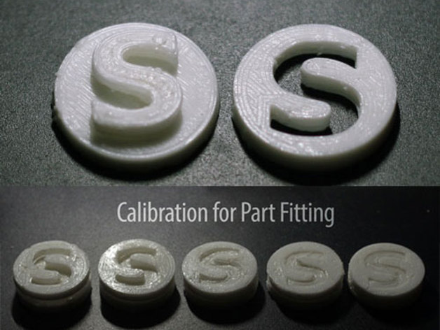
Do your print-in-place bearings, joints, hinges..etc, stick together on you ? Do you have nuts/bolts, screw threads, pegs and holes or gears that were supposed to fit and they don'?t? Well, those days are over after you run through this calibration for part fitting!From my observation, the main issues of the printed part being off-sized or parts where they're supposed to be separated got stuck together are: Extrusion width and Flow rate are not precisely calibrated, causing actual extruded thread width to be wider than what the settings expected. The Esteps/mm value is not properly calibrated. Z height is not properly adjusted, causing layers to get squeezed together by the nozzle. Hot-end and extruder printed parts are not screwed tight, causing the nozzle to off-set during printing. ...maybe more. There is a good guide from whitemousegary (http://www.thingiverse.com/thing:52946), he uses Skeinforge to do the part fitting calibration. Here we show how to do the same using Slic3r. Please note that this method is through my own trial-and -error that works for me. You are welcome to use any other ways that work best for you. Tasks: Run the Thin Wall calibration first to tune the extrusion. The point is to get the exact thickness of the wall that matches your nozzle diameter. And then you do the S-Plugs fitting test to fine tune the extrusion for better part fitting. For Thin Wall calibration: 0.2mm nozzle please use: http://www.thingiverse.com/download:614996 0.3mm nozzle please use: http://www.thingiverse.com/download:614997 0.4mm nozzle please use: http://www.thingiverse.com/download:614998 0.5mm nozzle please use: http://www.thingiverse.com/download:614999 ( I made these walls but other than the 0.4mm thin wall I haven't done the testing with them yet since I only have a 0.4mm nozzle installed for now. And I will use it for this demo.) (You can print a sample before the calibration adjustment for your reference) Do the ESteps/mm calculation. ( Remove the hotend from the extruder and heat it up. Send filament through the feeding hole of the extruder and tell the printer to extrude 30mm of filament. ) Measure the actual length extruded and get the: NEW ESteps/mm value = OLD ESteps/mm X 30 / actual extruded filament length measured. Store to firmware. Now we have a rough ESteps/mm value. Measure multiple parts of the filament diameter, get an average value and fill in the number in the corresponding area in Slic3r. Clean and plunge the nozzle. Set the temperature on the lower side for printing if possible. Speed should be under 30mm/sec. Set the layer height that matches your nozzle diameter (ex:0.4) Under Advanced tab in the Print Settings, set the Perimeter to 0.4 for Extrusion width and print. After it is printed and cooled, measure the walls and adjust the Extusion Multiplier in the Filament Settings, print again until you get the exact measurement ( or as close as you can ) of the walls that matches your nozzle diameter. BUT, if you've adjusted your multiplier lower than 0.9 or higher than 1.1 and still didn't get the ideal thickness, set the multiplier back to 1. It is time to adjust ESteps/mm. Please know that we are trying to ask the printer to give the correct width of the walls by using a fixed perimeter width value for this calibration. When we put in say 0.4mm from the settings, we want 0.4mm walls in reality regardless. So we fix the perimeter value and tweak the ESteps/mm and/or multiplier value ( in reality it means feeding more or less plastic into the heated hot-end ) until we get that result. And this means at least we can trust that the printer will extrude threads with the thickness which we expected from the settings we put in. However, we probably will run into situations like weaker printed objects, but we can fix that by adding more loops or change other settings after we get the correct thickness of the walls . Write down the current ESteps/mm for backup. Now lower the ESteps/mm if the walls you got were too thick and print again. How much to adjust depends on how far off your measurement is. Note that when extrusion rate is lowered, it is possible that your first layers become increasingly difficult to adhere to the bed. This is unavoidable. With more practice it should be easy to overcome. If that is the case, you can turn on the heatbed, re-adjust the gap between the nozzle and the bed, and applying some glue will help. Do anything you know to make it stick. Observe the printing closely. The first layer must be fairly successful. Make sure it is not being squeezed by the nozzle too much. Check if the exrtrusion is consistent. If the walls are sagging between the corners, or you are getting weak or holed printout, or the nozzle "seems" further away as layers build up to the point the threads don't even stick to the current layer any more, that means the extrusion rate is too low. Add some more steps back. Thin Wall calibraton done. The S-Plugs Fitting Test Now that you've got a good extrusion, you can try fitting the S-Plugs. If you've done the Thin Wall calibration properly, this test should not be too far off from your expectation. Print a sample for reference before tuning. Wait for it to cool off. Try fitting them together. Now go to Advanced tab in the Print Settings. Change the Perimeter value to 0.32 or even 0.28 for Extrusion width. This will make the perimeter width thinner, it will help bringing the perimeter resolution up and help with the parts to fit together more easily. But low extrusion also means it is more difficult to control. When we lower the perimeter width, the surface of the product might be weaker. So for other objects in the future you might want to add more perimeter loops and slow down your usual printing speed a little. The Infill and the Solid Infill width should stay at a decent width (around 0.4), if you set them too thin, they will affect the accuracy of the perimeter width. S-Plug Test done. Use flow rate control to fine tune the consistency of the extrusion for different types of objects in the future. Now you have a machine that prints more size-accurate. Go ahead and try those things that used to fail to work after printing, or try other challenging calibration and objects. The bearings, gears, hinges, screw threads, pegs and holes, nuts and bolts will now fit better and work for you. Hope this helps. For more information about this calibration, please visit: MEH4D Creation - http://meh4d.byethost32.com/?p=11
- 0 inches x 0 inches x 0 inches
- this product is 3D printed
- 16 available colors
- material is a strong plastic
- free delivery by Jul 06
- 0 parts