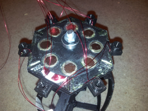
Small low power 3 phase A.C. / D.C. generator designed for low energy applications using wind or water power. The generator is stackable allowing you to build up a working system of multiple modules to provide the voltage or current required. Connecting a module in parrallel boosts the current and connecting in series boosts the voltage.Video now available from here: http://www.youtube.com/watch?v=zf6VWercbhwRequirements: 1 x Printed Rotor Plate 6 x Printed Coil Case 2 x Printed Magnets Bracket 2 x 8mm Nuts 4 x 8mm Flat Washers 1 x Length of 8mm threaded rod (you can pick this up from BandQ) 1 x 608 type thrust bearing (low cost on eBay) 16 x 18mm x 3mm Circular Rare Earth Magnets (Available From Farnell) 1 x Reel 0.4mm Insulated Copper Wire 1 x Tube of Strong Glue (I used EVO-STICK Multi-Purpose IMPACT glue)For each additional cell you require simply add: 1 x Printed Rotor Plate 6 x Printed Coil Case 1 x Printed Magnets Bracket 2 x 8mm Flat Washers 1 x 608 type thrust bearing (low cost on eBay) 8 x 18mm x 3mm Circular Rare Earth Magnets (Available From Farnell)Begin by placing and gluing each of the magnets in the magnet brackets. Each magnet should be alternated so they run north, south, north, south etc. Double check with a weaker magnet before gluing. Use plenty of glue and then leave this part for 24 hours to thoroughly dry.Next check that the coil cases all snap together correctly and ensure that they fit int the hole on the rotor. Using a long 3mm screw or piece of threaded rod fasten two large flat objects either side of the coil case. I used two thick gears I had already printed off for another design. Basically you just need to keep the outer of the coil case sandwiched together while keeping the edges from flexing outwards too much.There is a marker on one side of the coil case showing the direction to wind the copper wire. This helps to get all the coils facing the same way. Wind 250 turns on each of the coils keeping the wire fairly tight. At the end of 250 turns the wire should be just poking out of the sides of the case. Remember to keep a fairly long amount of wire free at each end of the coil say 20cm. When you have wound the coil unscrew the 3mm jig and place the coil case into the rotor. Repeat this process 6 times. Once you have all six coils sitting in the rotor you can insert the bearing. It should be a nice snug fit. Apply glue to the edges of the coil cases and bearing to glue them in place. Allow a few hours to dry and then flip the rotor over and glue the edges of the underside.Once everything has dried your ready to assemble the generator. Place a nut onto the 8mm threaded rod and then slide on one of the magnet brackets. After this slide on 2 washers (you may be able to get away with only 1 if your coil winding and gluing is accurate enough) followed by the rotor. Next another 2 or 1 washers followed by the second magnet bracket. The bracket should automatically align itself with the underside bracket. If you have any additional rotors and magnet brackets then add them now. Finally add another nut and tighten just past finger tight so the unit will not shake itself loose.To wire up as an AC generator the opposite coils need to be joined together to create the three phases for our generator. Take one of the wires from a coil and solder to one of the wires from an opposite coil. Use the soldering iron to remove the insulation from the wire. Use a AC multimeter or scope to get this correct, the voltage should double from that of a single coil when you turn the generator shaft. Repeat this three times for each coil to make 3 double coils. Then join one of the ends from each double coil together to form a central connection point. The remaining three wires are our three A.C. phases.To rectify the A.C. phase wires into D.C. simply add two fairly high current schottky rectifier diodes to the end of each phase wire. One of the diodes points up to the positive D.C. rail and the other diode points up from the negative D.C. rail. See bridge rectifier circuits for details.Currently only tested a single module using 250 turn coils, 18mm magnets and two washers between magnet bracket and the rotor. Parts printed using 0.3mm layer height and fairly flattened filament to form solid single layers. The test cell generates around 4V A.C. peak to peak at 3 revs per second (180 RPM). which I'm estimating should produce a rectified D.C. voltage of around 3.2V at said speed. Four cells combined together should therefore generate around 12.8V which should be great to power some of my embedded microcontroller PIC and AVR projects. I may have a play around with thinner wire and more turns on the coils to see what kind of benefits to the voltage this provides at lower operating speeds. What I don't want to do is add too much resistance so going too far with this would probably have negative repercussions.Sketchup files included.More testing and results soon....
- 0 inches x 0 inches x 0 inches
- this product is 3D printed
- 16 available colors
- material is a strong plastic
- free delivery by May 03
- 0 parts