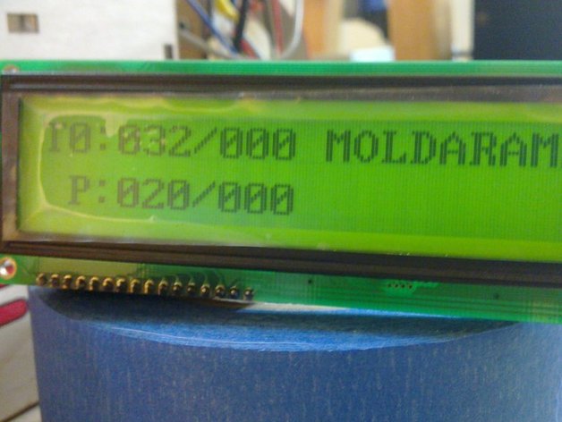
I don't know why Thingiverse puts the descriptions in this order and makes you read through my extreme verbosity just to get to some instructions...Cupcake users have been rigging up LCDs for a while, but as far as I (and the Firmware, and the RepG code) know, no one has done it on a Thing-O-Matic. I guess the latest RepG monitors temperatures, so that's nice, but I had this LCD in a box and I thought finally - something to use it on. Yes, this has no keypad, but even if you have /nothing/ in your workshop, the total project cost for this is < $20.It turned out to be a bit of a slog, since there was literally nothing written for it in the Thing-O-Matic firmware. But worse than that, since I personally have two extruders, and I hope others will follow ( http://www.thingiverse.com/thing:6632 ) ... it didn't make sense to hook it to the extruder controller as is traditional. It made sense to hook it to the motherboard.This brings in a whole raft of problems. The motherboard firmware has never known the toolhead temperature. It doesn't really have any way to know. So I had to add one. Because the only way to get the temperatures is a round-trip comm with the extruder, this is a little costly; but I think in the latest version I've managed to completely eliminate any delays.IMPORTANT NOTES FOR YOU!UPDATE: (2011-03-01)It does introduce delays. By splitting things up so that it doesn't try to do everything at once, the delays are vastly reduced, but not, I think, eliminated. However, there may be more I can do, and suggestions are welcome. I'll be uploading a new patch later tonight after I do some more work that will solve at least most of the problem.Patch still pending; I've uploaded a plan for a LCD Case, which so far I've printed the smaller half of and it fits great. I've got a plan for fixing the delay completely; it turns out the LCD library form Arduino is stupid and sits and waits after each character for 100us. Assuming this adds up pretty quickly, but the LCD actually does require almost 100us to process a command, the sane thing to do is to pulse the line on, go on and do something else, and come back after about 100us to turn it off. This is easy to accomplish and when I upload the patch it'll have this change, but it may not be for several hours as I'm knee-deep in my day job right now.-- new patch and firmware uploaded. These make a huuuuuuge improvement in how the LCD Library works, so there's fundamentally no delay there. But the querying of the extruders does still sometimes introduce a delay I still need to solve. I'm not sure how (or if - haven't used it myself) RepG is able to query for the temp during a print without causing minor interruptions... But I'm imagining the solution is something like putting a check temperature command into the queue instead of just /doing/ it like I am now... since that'll make it fundamentally equivalent to whatever RepG is accomplishing.So that'll be my next step... another pretty big one probably.UPDATE: (2011-03-04)Sorry for the delays on this one; my day job has been just killer lately and I've had to fit in ToM development where I can.I got the LCD display I linked below from Sparkfun, and it turns out some of the assumptions I made about how these things work generally, extrapolated from the one I was using, were incorrect. It's not any major thing; the one wire I hooked up 'even though it's not used' turns out to be an analog contrast adjustment pin on most of these LCDs, so should be attached to a pot to make an easy contrast knob; or maybe PWM'd from the pin it's on now would work? Not sure; I'll probably go with the pot...And a reason for that is I've recieved the $3 keypad mentioned in the comments. It needs 7 pins to drive. If you're keeping score at home, that makes 23 pins total used between the keypad and LCD, and the ToM expansion port only has 22 pins. If I take out the LCD contrast pin and run it through a pot, that frees up the final needed pin. However, I'm not doing that right now; I'm stealing the unused pin out of the x-max endstop.There will be an updated firmware up sometime today that shows the beginnings of keypad support and HOPEFULLY clears up the last of the delays from polling the tools. Incidentally, I looked over the cupcake LCD code by Revar to see how it was done there, and it seems to be on an unmaintained, outdated version of the code, sadly. (If I'm wrong, correct me!) It's too bad the stuff I'm putting together here is not likely to work for cupcake users without some modification. I did find some inspiration there for how to approach things overall, but not a lot, as that architecture is very different... not just that old firmware, but also his design -- it costs so much more to put together his because is uses i2c; it only needs a few pins to drive everything. Here the total cost is < $20 in dollars but about 22 in pins. Still, what ELSE are you going to use all those pins for? No beginnings of keypad support in the code /as such/ but you will find the firmware below now clears up all delays... so it works perfectly as advertised.UPDATE: (2011-03-05)Tested with 16x2 display from Sparkfun: http://www.sparkfun.com/products/709This should also apply to the following (at least): http://www.sparkfun.com/products/255 http://www.sparkfun.com/products/791 http://www.sparkfun.com/products/790 http://www.sparkfun.com/products/256 4 lines!I needed to tweak the firmware just the tiniest amount to fix up the support for the Hitachi standard, as the 20x2 Newhaven I had been using has some odd quirks. Now the patch should support either one, but the firmware below is compiled for the 16x2 from Sparkfun -- oops, and two toolheads. I'll recompile and upload it again shortly. As always, it's best if you can use the patch and compile your own!I've uploaded some comparison photos.The case I made for the sparkfun LCD failed to take into account the extended length of the backlighting, and so does not fit. I don't need to upload it; it's the same code as the other case just with the measurements changed.I do still owe you all a new firmware, and I'll upload it tomorrow. I've got the keypad (linked below in the comments) up and running and I expect Big Things for tomorrow!UPDATE: (2011-03-06)I'm putting a DONE stamp on this. As a temperature readout for the Thing-O-Matic, it's complete and there are no issues I am aware of remaining. The published version of the firmware below is compiled with the patch labeled "finalprobably," which is just what it says. 1) Get an LCD that is compatible with a "Hitachi HD44780" chipset. This is basically any character-driven LCD display that has 8 data lines plus a RW, RS, and E. Mine is a NHD-16032AZ-FL-YBW from Newhaven Display, which I like because they are local so if it breaks, I can go throw a rock through their window. The comm chipset on this is a "ST7920" which is compatible with the beforementioned chipset, so it's all good. This particular chipset can do actual graphics and things as well on top of what the standard supports, but this build doesn't take advantage of that (yet). Here's a link to mine at digikey. It's been in a box so long I can't remember where I got it now, but it was likely there: http://search.digikey.com/scripts/DkSearch/dksus.dll?site=us〈=en&keywords=nhd-16032az-fl-ybw&WT.srch=1 Here's a link to one that's compatible but I think seems much cooler-looking at sparkfun: http://www.sparkfun.com/products/7092) Figure out a good way to plug it into the big IDC port on the ThingOMatic Motherboard. You'll see my solution here in the photos, I just got a bunch of little 5-pin female connectors, because they were what I could find, and chopped them up and wired them to fit the 16 pins on my LCD. YOu might have fewer pins; this particular LCD has one pin I wired even though it's not used, as well as two GND and +5v pins (which you'll see in the photo I crammed together into one connector on the mobo end).Once you have you PLAN on HOW to connect it, you have to sit down and make a little chart so you know which pin on your LCD is which pin on the motherboard. Here's the chart I wrote up:1 GND 2 +5v 3 NC -> 3 4 RS -> 4 (c,3) 5 RW -> 5 (c,2) 6 E -> 7 (c,0) 7 0 -> 9 (g,2) 8 1 -> 11 (g,0) 9 2 -> 13 (l,6) 10 3 -> 6 (c,1) 11 4 -> 8 (d,7) 12 5 -> 10 (g,1) 13 6 -> 12 (l,7) 14 7 -> 14 (l,5) 15 +5v 16 GNDThis is: PIN NUMBER ON LCD, PIN NAME/PURPOSE ON LCD -> PIN ON ToM MOBO (PORT AND PIN ON ARDUINO)IF YOU ARE USING MY COMPILED FIRMWARE, YOU'RE GOING TO HAVE TO USE THE SAME PINS I DID, SO FOLLOW MY CHART. Good Luck. (Notice pins RW-2 are all aligned on the mobo end and pins 3-7 also.) On the other hand, if you're using my firmware, once you have it wired, you're done. If you are able to compile your own firmware with my patch, I highly recommend it. It will allow you to connect the wires anywhere you see fit, instead of where I thought was good. It will also allow you to put in a little message where you see "MOLDARAMA" and "SCRIBBLE" in my photos.You need this chart or a similar one for your own wires. Get the left-hand side by looking on the silkscreen on your LCD, or on the datasheet. My datasheet is here: http://www.newhavendisplay.com/specs/NHD-16032AZ-FL-YBW.pdfGet the right-hand side by looking where you want to put your wires, and using the section on this page: http://wiki.makerbot.com/thingomatic-doc:makerbot-motherboard-2-4 -- you want the part labeled "INTERFACE CONNECTOR" and the table and photo should make it REALLY EASY to build your little chart of where your wires are going. Except for the 5v and GND connections, it doesn't matter where you hook them up, you can put them anywhere, just make sure your chart has the right port and pin to go with the place you plugged each wire in.3) First, apply my patch, below, to your firmware source tree. If you don't know how to do that, I'll post directions.Then, edit the file v2/src/Motherboard/boards/mb24/Configuration.hh and look for the section that begins "#define HAS_LCD"You'll see here that there is a map between the pins on the LCD and the pins on the ARDUINO, so you need to put in the Port and Pin assignments you got from the charts on the wikipage.Below that are options to tell it how many toolheads you have, and which toolhead index is the one with the heated platform. You can also set a few letters to fill the extra space to the right of the temperature readout, on my system I have room for one space plus 9 letters, so " MOLDARAMA" just fits and I need to tell it that's 10 characters on the next line.After you change the settings, just compile it and upload it to the machine. If your LCD is already hooked up, it'll start working right away (well, after 1 second)!5) THE OUTPUT.... is TX:YYY/ZZZ where X = toolhead index (starts at 0) and YYY = current temperature, ZZZ = set temperature. This is repeated per line for each extruder in the system (so you need an LCD with 4 lines for 4 extruders!), then it prints out P:XXX/YYY where XXX is the platform temperature and YYY is the set temperature.Of course if you compiled your own firmware, it will also print your message after the first TX:YYY/ZZZ.-- The above is only true for the Newhaven 20x2 display; the smaller 16x2 from Sparkfun is a little more condensed, and leaves out the toolhead index -- you can figure it out from the line.
- 0 inches x 0 inches x 0 inches
- this product is 3D printed
- 16 available colors
- material is a strong plastic
- free delivery by Jul 17
- 0 parts