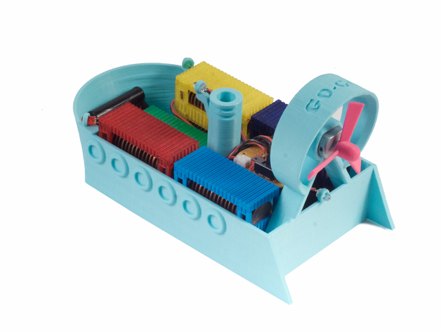
Designed by David ChoiI wanted to create an educational piece that one can learn from and expand on, by developing and enhancing fundamental and motivational experiences while building, testing, and playing. Mathematics, physics, and electronics weren't the easiest things for me to learn, but I think with passion you can learn anything, and this can be rapidly fueled by successful, real-world experiments that are made fun. This introductory project is geared towards young minds, novices, students, DIYers, enthusiasts, the different, and the like, for exploration, experimentation, and positive iteration. *My current extruder tends to ooze on outlines so I lowered the temperature and decreased the speed around outlines. We want to calculate the maximum number of pennies we can load onto the GO-GO AirBoat before it begins to sink. Hopefully your GO-GO AirBoat will shove off before it reaches this maximum penny value. Since we're loading the pennies into cargo containers, it'd be nice to predict if our next container will lead to a sunken disaster or not. Boats float due to their buoyancy in water. Buoyancy is a function of the volume of the fluid displaced and the density of the fluid displaced, along with the local acceleration due to gravity. The less dense object will be more buoyant (float), and the denser object will be less buoyant (sink). In our case, so long as our boat is less dense than the water it displaces, it will stay afloat! So let's figure out the maximum number of pennies we can load using any configuration of cargo containers... All pennies have an average mass of 2.5g. Density = (Mass) / (Volume) "Density of Water" = Dwater ? 1g/cm^3 "Mass of a Penny" = Mp = 2.5g Note that at sea-level on Earth, "weight" [kg] and mass [kg] are interchangeable... ? "Weight of a Penny" [kg] = Wp [kg] ? Mp [kg] This is important since we'll be doing several weight measurements later on (most likely you're using a spring scale or digital scale) but we'll be needing their masses instead for our equations and calculations. We'll use this mass-to-weight relationship to help simplify calculations. You may already do this conversion automatically in your head and never think twice about it, but it's a good idea to understand why we can do this on Earth. This explanation also helps us see why notation and the true meaning behind the notation is so important in physics problems. Balances measure mass directly by canceling out the local gravitational force on either side of the fulcrum, but you need a known, calibrated mass to measure against. Your household spring scales and digital scales, on the other hand, directly measure forces, namely weight. You probably have a spring scale or digital scale and not a balance, so we're going to say these measurements are of mass for simplicity's sake. This is a valid approximation for our sea-bound GO-GO. Let, x = "Maximum Number of Pennies" We want to solve for the maximum number of pennies the GO-GO AirBoat can carry. So this means we need to solve for the variable x, where the density of the volume displaced by the ship is less than the density of water--that's almost the boundary where our ship floats or sinks. We need to solve for x when: Dgg < Dwater, where Dgg is the "Density of the Loaded GO-GO." To do that, we'll first need to find out what the "Total Mass of Loaded GO-GO" (Mtotal) is, since it can be seen that Dgg = (Mtotal) / (Vd) from the Density equation, where Vd is the "Volume Displaced." Let, Vd = "Volume Displaced" = ( ? cm^3); Where, 1mL = 1cm^3. Let, Mgg = "Mass of GO-GO with Electronics and Battery, Unloaded" = ( ? g) Let, Mcc = "Mass of a Cargo Container, Unloaded" = ( ? g) Let, Mcl = "Mass of a Cargo Lid" = ( ? g) A method to measure the full displacement of the ship at capacity would be to put a large bowl inside a larger empty bowl, fill the inner bowl to the brim with water, and dunk the boat to the desired depth (the maximum depth you think the GO-GO can handle, or when the depth sensor is triggered--these are designed to be similar in value). Any displaced water caught in the outer bowl can now be measured off with a measuring cup or even better, weighed with a scale. For some reason I don't actually have any bowls, measuring cups, a scale, or any basic kitchen utensils in my apartment so I never tried this myself. An alternative, less useful method is to just measure the volume of the inside of the cargo area of the boat hull alone. This will clearly give you an incorrect, undesirable, or otherwise completely wrong answer but this can be done with a small measuring cup swiftly. Your calculation will be off by a decent number of pennies, possibly resulting in a sunken ship. Just keep this in mind. Let, a = "Number of Cargo Containers" Let, b = "Number of Cargo Lids" "Total Mass of Loaded GO-GO" = Mtotal = (Mgg) + a • (Mcc) + b • (Mcl) + x • (Mp) Recall, from the equation for Density, we have... "Density of Loaded GO-GO" = Dgg = (Mtotal) / (Vd) ? Dgg = [ (Mgg) + a • (Mcc) + b • (Mcl) + x • (Mp) ] / (Vd) So how do we relate to the "Density of Loaded GO-GO" (Dgg) then? Remember our stipulation for solving for x? (Hint: "We need to solve for the variable x, where the density of the volume displaced by the ship is less than the density of water--that's almost the boundary where our ship floats or sinks.") I know what you're thinking. You're right. We need to find Dgg < Dwater, and we know Dwater ? 1g/cm^3. ? Dgg < Dwater ? [ (Mgg) + a • (Mcc) + b • (Mcl) + x • (Mp) ] / (Vd) < (Dwater) ? x < [ (Dwater) • (Vd) - [ (Mgg) + a • (Mcc) + b • (Mcl) ] ] / (Mp) ? "Maximum Number of Pennies" < [ (1g/cm^3) • (Vd) - [ (Mgg) + a • (Mcc) + b • (Mcl) ] ] / (2.5g) ? ? If the number of coins that you load onto GO-GO AirBoat is less than the right-hand side of the above equation then your GO-GO will stay afloat in water!... Right? Almost: The answer must be an integer value since we are talking about whole pennies, not partial pennies. (Why minus one penny? Since an integer value is an indication that the values are exactly equal even with rounding of the "Maximum Number of Pennies," we need to subtract one whole penny in order to satisfy the inequality.) For this project I went to RadioShack. The JST connector I had on hand from Adafruit. The motor I had around from somewhere but Adafruit carries a very similar one. You can also use these awesome sites below: The main components of the electric circuit are an infrared (IR) emitter-phototransistor pair; the NPN, Darlington transistor pair; and the DC motor. Those are the important parts. The circuit can be broken down into 5 smaller sections to cover every part's function. I've provided the circuit diagram as two separate diagrams included in the image files for GO-GO AirBoat. The first diagram is of the main driving circuit and sensor. The second diagram is for the decorative LED's. R1 = 1k?, 1/4W Resistor R2 = 100?, 1/4W Resistor R3 = 1k?, 1/4W Resistor R4, R5 = 220?, 1/4W Resistor IR LED = 1.2Vfwd, 100mA max C = 1,000uF, 10V Electrolytic Capacitor D = 1N914 Diode M = 4.5V - 6.5V DC 130-Motor, 250mA PT = Phototransistor, 50mA max, 150mW max Q1, Q2: 2N2222; 600mA continuous, 625mW max The Power Supply and Main Power Switch This is the simplest section to explain. This circuit is extremely basic and utilizes no proper voltage regulation. That's why battery voltage selection is important. The power supply is a constant voltage battery of 3.6V with a power switch connected in series. The polarized, electrolytic capacitor in parallel with the whole circuit is there to help smooth current draw from the battery and prevent supply voltage dips across the rest of the supply when the motor turns on. It's main purpose in this circuit is to prevent the LED's from flickering too much when the motor turns on. A dedicated voltage-regulating chip would help cure this with the help of a slightly higher supply voltage requirement. The DC Motor and Flyback Diode The circuit is designed around the 4.5V motor and its current draw. We'll need to be sure the transistor Q2 can handle the power dissipation, which we'll calculate later on. See the "Bipolar Junction Transistors (BJT's) and the Darlington Pair formed by Q1 and Q2" section for calculations for the motor and transistors. The flyback diode protects the supply and transistors and decreases back EMF generation by the motor. It's common practice to put one in reverse, in parallel with the motor terminals for a single-direction DC motor. If you happen to try to run the motor in reverse, you'll blow the diode from excessive current. The LED's and IR Transmitter Diode The red and green LED's have 220? resistors in series with them, the IR transmitter diode has a 100? resistor, and the white LED's share a 1k? resistor because they're very bright. The forward voltage drops of LED's are different based upon different LED output powers and their respective colors, which makes 220? a safe working point. However, they may appear a bit dimmer than you'd like, but you can adjust for your LED's accordingly by following the instructions given in a moment. The IR transmitter diode works just like any other LED. If you would like to calculate resistor values for your own LED's, follow this formula: First measure the forward voltage drop of your LED (Vfwd). Some LEDs provide this information on their packaging or datasheet. Vfwd = "Your LED" [V] (It may be 1.2V to 1.7V for example. Use your diode checker or refer to a datasheet) Vs = "Your Supply Voltage" [V] (This is 3.6V in our case) I = "Your LED current" [A] (Typically 10mA to 25mA for your basic LED depending on desired brightness) Following from Kirchhoff's Rule for our series resistor and LED circuit, we know... ? Vs = (Vfwd) + (Vresistor) ? Vresistor = (Vs) - (Vfwd) From Ohm's Law, we have... V = I • R ? R = V / I ? R = (Vresistor) / I ? ? R = (Vs - Vfwd) / I Example: R = (3.6V - 1.2V) / (0.025A) = 96? So, 100? will work just fine for our IR transmitter diode--it's the closest, common resistor value. Note: Since the white LED's are so bright, I wired the two, white LED's in parallel and then in series with a single, current limiting resistor of 1k?. This effectively halves the current provided to each LED individually, resulting in a dimmer light that better matches the outputs of the not-so-great red and green LED's I used. This saves us from needing another resistor. See the schematic for clarification. Extra Exercise for Beginners: Bipolar Junction Transistors (BJT's) and the Darlington Pair formed by Q1 and Q2 Our goal is to calculate the necessary base current (Ibase) to be supplied to our motor with a 2N2222 (in our case, in a Darlington pair configuration). Relevant 2N2222 specifications: Q, max power dissipation = 625mW Q, continuous current = 600mA Q, ? = 10 Q, Vce ? 0.1V @ (Ic / Ib) = 10 Our motor will draw around 150mA so one 2N2222 will be enough. We have a second transistor, Q2 wired to transistor Q1 in a fashion called a Darlington Pair. A Darlington pair acts as a gain multiplier. Essentially, you can multiply the two gain factors (?) of Q1 and Q2 together to create a very sensitive amplifier stage we'll call Qd (which consists of Q1 & Q2). So our new Darlington gain (?, Qd) is... (?, Qd) ? (?1 • ?2) ? (?, Qd) ? 10 • 10 ? (?, Qd) ? 100 Darlington pairs, because of how they are constructed, have a different (Vce) than a single transistor. For Darlington Pairs... (Vce, Qd) = (Vce, Q2) + (Vbe); where (Vbe) = 0.6V (Minimum for saturation) ? (Vce, Qd) = 0.1V + 0.6V ? (Vce, Qd) = 0.7V Updating our specifications for Qd as a whole, we have... Our new Darlington pair 2N2222 specifications Qd: Qd, max power dissipation = 625mW Qd, continuous current = 600mA Qd, ? = 100 Qd, Vce = 0.7V Using the power formula we can calculate the power dissipation of transistor Q2 when drawing 150mA to check if it is in range... Ice = 0.150A P = I • V ? Pdissipated (of Q2) = (Ice) • (Vce, Qd) ? Pdissipated (of Q2) = 0.150A • 0.7V ? Pdissipated (of Q2) = 0.105W = 105mW ? [ Pdissipated (of Q2) = 105mW ] < [ Q, max power dissipation = 625mW ] Now that we checked our transistor won't overheat, we can finally calculate the amount of current that needs to be supplied to the base (Ibase) of Q1 in order to drive our motor with 150mA. (We don't have to evaluate the power dissipated in Q1 because it is easy to see that this is a very small amount). Using the following formula, where (?, Qd) = 100... Ibase = (Ice) / (?, Qd) ? Ibase = 0.150A / 100 ? ? Ibase = 1.5mA This means the resistor R1 must pass at least 1.5mA in order to fully turn on our Darlington pair. Also, our phototransistor must be able to sink at least this much current in order to fully turn the transistors off. Before moving on, we must calculate the voltage across the base and emitter for a Darlington pair (Vbe, Qd). (Vbe, Qd) = (Vbe, Q1) + (Vbe, Q2) Where, (Vbe, Q1) = 0.8V (at 150mA) (Vbe, Q2) = 0.7V (at 15mA) ? (Vbe, Qd) = 0.8V + 0.7V ? ? (Vbe, Qd) = 1.5V We need to know (Vbe, Qd) because this is the voltage threshold needed to turn the transistors Qd fully on. The Phototransistor Trigger Phototransistor specifications: I = 50mA max P = 150mW max What we want is for Qd to turn on when the IR beam is blocked; that is, when the phototransistor stops conducting. Therefore, the phototransistor is wired in series below the 1k? resistor. The node between the phototransistor and 1k? resistor where the base of Qd connects is our node of interest (Q1's base). The 1k? resistor (R1) is our base resistor for Qd. We need the base resistor to pass at least 1.5mA when the phototransistor is in the on-state, and pass at least 1.5mA to the base of Qd when the phototransistor is in the off-state. In other words, at least 1.5mA must be flowing through the R1 at all times. This current is small compared to the 50mA max throughput for our chosen phototransistor, so we'll have no problem switching the current to turn Qd on and off (even if we can't sink a full 50mA through the phototransistor.) We need R1 to supply at least 1.5V across the base and emitter (Vbe, Qd) to put Qd into a conductive on-state. Additionally, so long as the voltage across the conducting phototransistor (Vpt, ON) is less than the voltage across the base and emitter (Vbe, Qd), we can be sure the transistor Qd will remain in an off-state. This is due to the fact that the phototransistor is in parallel with the base and emitter of Qd. ? If [ (Vpt, ON) < (Vbe, Qd) ], then "Qd is OFF" ? ? If [ (Vpt, ON) < (1.5V) ], then "Qd is OFF" Solving for the phototransistor (PT) in the on-state (where Qd is off)... We know: Vcc = 3.6V (Vpt, ON) < 1.5V; (This is our Qd off-state condition) We need to find a (Vpt, ON) < 1.5V where our phototransistor remains conducting. We're in luck because I was planning ahead: Let, (Vpt, ON) = 0.6V (I measured this for my IR LED in series with 100? (R2) and distanced about 1cm from the phototransistor.) Let's check our work: When the phototransistor is not conducting (IR beam blocked), current to the base of Qd is 1.5mA... Let, Ibase = 1.5mA Vr = (Vcc) - (Vbe, Qd) Vr = I • R ? R = (Vr) / (Ibase) ? R = [ (Vcc) - (Vbe, Qd) ] / (Ibase) ? R = (3.6V - 1.5V) / 0.0015A ? ? R = 1.4k? We don't want to use 1.5k? because it will limit the amount of current we get, so 1.2k? will work. I used 1k? in the final circuit because I have a lot of them and that works too. When the phototransistor is conducting (IR beam not blocked), current through the phototransistor (Ipt) is... Vr = (Vcc) - (Vpt) Vr = I • R ? Ipt = Vr / R ? Ipt = [ (Vcc) - (Vpt) ] / R ? Ipt = [ 3.6V - 0.6V ] / 1k? ? ? Ipt = 3mA ? ? Our 1k? resistor should be sufficient to turn Qd off when the phototransistor is conducting (IR beam unblocked) since [ (Ipt = 3mA) > (Ibase = 1.5mA) ]. So what all this means is, our phototransistor when blocked by the piston, will stop sinking 3mA to ground with 0.6V across it, allowing 1.5mA to pass into the base of the Darlington pair (base of Q1) with 1.5V across the base and emitter. This means our transistors are turned on and delivering power to the motor. MECHANICAL ENGINEERS & DESIGNERS PHYSICISTS & MATHEMATICIANS COMPUTER SCIENTISTS ELECTRICAL ENGINEERS I hope this walkthrough was complete enough for you to have built an understanding of the inner workings of your GO-GO AirBoat. In this project you strengthened your expertise in: Integrate what you've learned into your next 3D-printed project or next experiment and share your results! If I made a mistake anywhere that led you down a dark, dark path... either up in smoke or under the waves, let me know where and I'll fix it.
- 0 inches x 0 inches x 0 inches
- this product is 3D printed
- 16 available colors
- material is a strong plastic
- free delivery by May 02
- 0 parts